INTRODUCTION
CIVIL Design is a software integrated in AutoCAD. This allows the design of roads, of civil and non-transport infrastructures (railways, quarries, landfills, dams, maritime works, sewers and aqueducts, topography, vector and raster cartographic management, i.e. Regional Technical Map, orthophotos, satellite photos or cadastral maps) useful to allow designers to manage any image format. Georeferencing of vector entities is also possible, as well as the superimposition of CAD projects on aerial photos and also create a final merging image. This software is suitable for both project management and the management of the execution phases of the work (topographical surveys, land registry, variants, site accounting …) thanks to a countless catalog of possible operations such as Editing, Rototranslation, Mosaic and much more.
ADVANTAGES
- The ability of the software to be used daily by thousands of technicians operating in the area, such as surveyors, infrastructure designers, construction companies, design companies, makes it possible to offer a complete 360-degree design.
- To ensure that all collaborators have a better interface with the software, a paper tutorial is added which describes the operations considered basic and the most used; there is online help for the use of individual commands combined with a video course held by technicians.
- An average AutoCAD user, with the necessary technical skills, immediately begins to be operational since the approach is the same as drawing in AutoCAD. This results in a saving in terms of time and money for a learning period. However, courses are available for those who need them.
PRODUCT DESCRIPTION
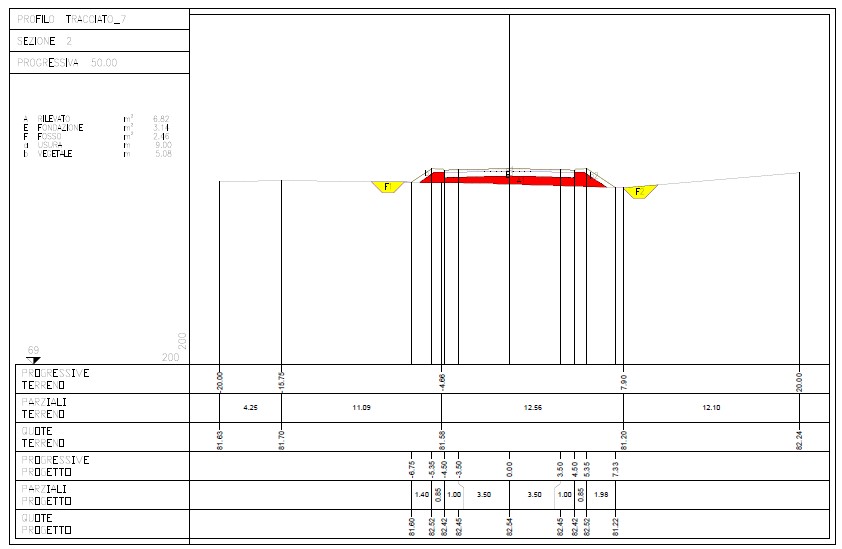
In the design phase, it is allowed to insert standard sections, which include any number of polylines, with the possibility of automatically connecting the project with the ground.
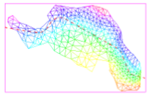
Surf also provides functions for calculating the volume of an area of territory with the “prism” method: it allows you to delimit a triangle model area with a perimeter to calculate the volume subtended by the model inside the perimeter with respect to a height assigned.
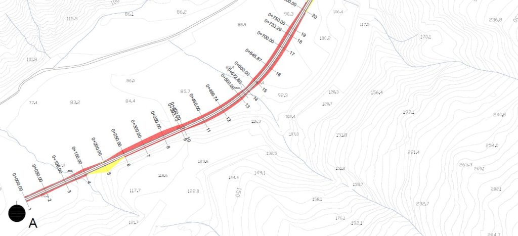
The three-dimensional representations can also be used for the assessment of environmental and visual impact. To date it represents the most powerful and complete Italian application of Autocad for the design of roads and railways. It is necessary to use as a basis for the project a cartography for the definition of the layout of the work, which can be both a topographical and a cartographic survey.
Equipped with very fast algorithms, it guarantees undisputed efficiency in the design, with the possibility of inserting an infinite number of artifacts.
MODELING
Sections
Parametric elements are freely drawn and can represent road, railway or any other artifact sections (retaining walls, embankments, ditches, canals, ramps, railway shapes, etc.).
There is also the possibility of producing printouts that can be used as attachments.
The two-dimensional and three-dimensional working method brilliantly solves the technical design problem and the problem of three-dimensional visual rendering for visual impact assessments.
- To define a project section, simply draw polylines to represent the current section and the marginal elements (ditches, gutters, walls …) and from these the program will insert them in the project sections respecting the conditions imposed, even in the presence of sections of complex project.
- The program has the possibility to automatically create the calculation sections, the section book and the report file of the calculated quantities.
- Sections are dynamic with respect to changes made in plan, elevation or other elements of the project.
Profiles
They allow you to quickly draw and dimension an elevation profile.
The available functions can represent on an unlimited number of altimetric and structural trends, such as levels, vertical connections, hydraulic works and more, heights, slopes and differences in height. All drawing operations take place in real scale.
An unlimited number of section families can be inserted on the profile, corresponding to which it automatically calculates the elevations on known polylines. The profile design can be integrated with artifacts and other descriptive elements.
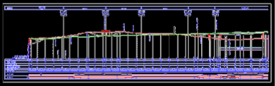
- The program allows you to create digital models with contour lines, triangles or regular mesh. Subsequently it is possible to extract a longitudinal profile of a path and report it in a title block; more generally, it is possible to extract profiles along any polyline.
- The program allows you to dimension the vertical junctions of road profiles respecting the visibility checks imposed by the legislation.